Pages

Subscribe:
Showing posts with label proteus tutorial. Show all posts

Saturday, 23 July 2011

Digital Clock Using Microcontroller 89C52/89S52


Are you a beginner in micro controller projects?and are you stuck where to start from?if yes,then this is one of the simplest mini projects that you can start from . This mini project will give you a clear understanding of programming your micro controller. we sometimes look at our watch and wonder " how does this thing work". Well, in this digital clock project, you will gain some insight on how micro controller can be used to make it work as a Digital Clock.

Components required:

  • 1 microcontroller 89C52(89S52 will also do)
  • 2 ceramic capacitors-22pF
  • 1 switch(button for reset purpose)
  • 1 electrolytic capacitor-10uF,25V
  • 1 crystal oscillator-11.0592MHz
  • 16x2 LCD display
  • 1 resistor-10k


Circuit diagram


Software you will need

This project has been done in proteus software.If you are new to proteus software, the tutorials given below may get you started with the software.note:if you are familiar with proteus you can skip this part.


The programming of the microcontroller is done using keil compiler.port 2 of 89C52 is used as the output port.whereas port 1 is used as the input port.when P1_4 is grounded the 12 hr mode is activated and when P1_5 is grounded the 24 hr mode is activated.In the schematic diagram P1_5 is grounded so the 24hr mode is activated.it is as shown below


Code:


The detail explanation of the code is done below:


#include "REGX52.H"
#include "delay.h"
#include "lcd.h"
void main(void)
{
int hr=0; /*initiate hour=0 */
int min=0; /*initiate minutes=0 */
int sec=0; /*initiate seconds=0 */
P1=0xff; /*set port 1 as input port */
P2=0x00; /*set port 2 as output port*/
while(1)
{ LCD_INIT(); /*initialize LCD*/
if (P1_4==0)/*if P1_4 is grounded enter the 12hr loop */
{
for (sec=0;sec<60;sec )
{
LCD_DisplayNum(hr,2);
LCD_STRING(":");
LCD_DisplayNum(min,2);
LCD_STRING(":");
LCD_DisplayNum(sec,2);
LCD_STRING(" (12 HR)");
delay_sec(1);
LCD_CLEAR();
if (sec==59)
{
min=min 1;
if(min==60)
{
if(hr==11&&min==60&&sec==59)
{hr=0;min=0;sec=0;}
else
{ hr=hr 1;
min=0;}
}
}
} }
else
{
if(P1_5==0) /*if P1_5 is grounded enter the 24hr loop */
{
for (sec=0;sec<60;sec )
{
LCD_DisplayNum(hr,2);
LCD_STRING(":");
LCD_DisplayNum(min,2);
LCD_STRING(":");
LCD_DisplayNum(sec,2);
LCD_STRING(" (24 HR)");
delay_sec(1);
LCD_CLEAR();
if (sec==59)
{
min=min 1;
if(min==60)
{
if(hr==23&&min==60&&sec==59)
{hr=0;min=0;sec=0;}
else
{ hr=hr 1;
min=0;}
}
}
} }}
LCD_INIT();
}
}


you can download the .hex file here

schematic diagram
main.c
digclk.hex


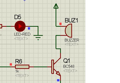
you can add more functions to this digital clock since 2 ports of 89C52 are still unused.For instance, you can connect a buzzer to port 4 such that the buzzer sounds at a specified time or you can connect a keypad to port 0 such you can set the timings externally.

Please comment if you would further like to improve the project.

Friday, 22 July 2011

Interfacing Of a Buzzer Using Microcontroller 89C52/89S52


Welcome back embedded system geeks! In this article we are going to learn about the interfacing of a Buzzer with the microcontroller. But if this is your first mini-project you should probably check-out my previous article on Blinking LED'S for more understanding of the programming I will be dealing with this project. Once you get to know what Buzzer is and the programming logic behind connecting a Buzzer and a microcontroller you will able to apply the same logic to any microcontroller (i.e. your microcontroller may be a PIC or an AVR microcontroller). At the end of the explanation of the code there are some questions for you to answer which can help you to improve your programming skills.


why do we need a Buzzer? 

Buzzer is used many times in embedded systems. For an instance-Digital clock with an alarm-here buzzer can be used an alarm or a fire alarm or an intruder alarm. There are so many uses.

Components required

  • 1 microcontroller 89C52(89S52 will also do)
  • 1 potentiometer-10k
  • 2 ceramic capacitors-22pF
  • 1 switch(button for reset purpose)
  • 1 electrolytic capacitor-10uF,25V
  • 1 crystal oscillator-11.0592MHz
  • 1 resistor-10k
  • 5 LED's
  • 1 resistor-1k
  • 5 330 ohm resistor
  • 1 Buzzer
  • 1 transistor-BC548


Schematic Diagram 


This project has been made using Proteus software.If you want to learn more about the software you can watch the tutorials provided below

 The connection of the circuit is explained below

  • Port 2 of the microcontroller is defined as the output port
  • Port 3 of the microntroller is defined as the output port
  • 4 LED's are connected to the four pins of the output port 2 from P2.0 TO P2.3 respectively
  • An LED is connected to the pin 3 of the output port 3 of the microcontroller
  • A Buzzer is connected to the pin 8 of the output port 3
  • Other components connected to the microcontroller are for the working of the microcontroller.
   

Working      

   
The working of the circuit is shown with an application of a decade counter. As soon as the microcontroller receives a power supply, the counter will start counting. An image of the counter is shown below


The Decade counter will count from 0 to 9 and when the counter counts 9, the buzzer will be switched ON.The transistor connected to the buzzer acts as a switch.The programming of the microcontroller is explained below:

#include "REGX52.H"
#include "delay.h" /*delay header file is included*/
void main()
{
P2=0X00;/*port 2 is defined as output port*/
P3=0XFF;/*port 3 is defined as output as port*/
while(1)
{ P3_2=0; /*set pin 3 of port 2 to logic 0 */
P3_7=0; /*set pin 8 of port 2 to logic 0 */
P2=0X00; /*code for the decade counter begins here*/
delay_sec(1);
P2=0X01;
delay_sec(1);
P2=0X02;
delay_sec(1);
P2=0X03;
delay_sec(1);
P2=0X04;
delay_sec(1);
P2=0X05;
delay_sec(1);
P2=0X06;
delay_sec(1);
P2=0X07;
delay_sec(1);
P2=0X08;
delay_sec(1);
P2=0X09;
delay_sec(1); /* code for decade counter ends here*/
if(P2==0X09)
{ P3_2=1; /*LED is switched ON*/
P3_7=1; /*buzzer is switched ON*/
delay_sec(3); /*buzzer is switched ON for 3 seconds*/
P3_2=0; /*LED is switched OFF*/
P3_7=0; /*buzzer is switched OFF*/
}
}
}


Try this for Fun      

Try to program your microcontroller in which the Buzzer is used as a musical device meaning your buzzer will output a musical tune .

Download files    

schematic diagram


what do you feel about the article?     

Please comment if you have any doubts or want to improve the project further


Chasing LED's Using Microcontroller 89C52/89S52


This mini-project is especially meant for a newbie in Embedded Systems. This project will give you a clear idea of how to think and implement your code in practical life. In this article, we will cover the programming details for LED blinking and how you can code your microcontroller to show different patterns of LED blinking. After learning the logic for LED blinking you can code any microcontroller with the same logic.


Components

  • 1 microcontroller 89C52(89S52 will also do)
  • 1 potentiometer-10k
  • 2 ceramic capacitors-22pF
  • 1 switch(button for reset purpose)
  • 1 electrolytic capacitor-10uF,25V
  • 1 crystal oscillator-11.0592MHz
  • 1 resistor-10k
  • 8 LED's
  • 8 330 ohm resistor
  • 2 switches (SPST) 

 Schematic Diagram


Softwares Used: 

This project is made with the help of Proteus software. If you are unaware of the software you can learn the basics by watching the video tutorial that I recommended in one of my articles.


The connection of the circuit is explained below:

  • Port 1 of the microcontroller is used as the input Port
  • Port 2 of the microcontroller is used as the output Port
  • The LED's are connected to the output of Port 2
  • Two switches are connected to the input of Port 1
    one switch is connected to the 5th pin of the Port 1 whereas the other switch is connected to the 8th pin of the Port 1
  • Other components like the crystal and switch are used for the working of the microcontroller


Working:

The programming is done using Keil compiler. The circuit is configured for two modes namely (1) The LED Blinking mode and the (2) Chasing LEd mode.when the switch connected to the 8th pin of the Port 1 is closed , the microcontroller works in the Blinking mode wherein all the LED's glow simultaneously for one second and remain switched off for the other one second and this process continues as long as the microcontroller is receiving the power supply .The blinking LED's are shown below:


When the switch connected to the 5th pin of the micro controller is closed and the switch connected to the 8th pin is open, the micro controller works in the Chasing LED mode i.e. the LED's glow one after the another for a second and looks something like this:


Programming:

The detail explanation of the coding is done below


#include <REGX52.H>
# include"delay.h" /* header file of the delay is added */
void main()
{ P1=0xFF; /*Port 1 is defined as input*/
P2=0x00; /* Port 2 is defined as output*/
while(1)
{/* code for the chasing LED's */
if(P1_4==0)/* if switch connected to P1_4 is closed*/
{ P2=0X01; /*glow the LED connected to P2_0 for 1 sec*/
delay_sec(1);
P2=0x02; /*glow the LED connected to P2_1 for 1 sec*/
delay_sec(1);
P2=0x04;
delay_sec(1);
P2=0x08;
delay_sec(1);
P2=0x10;
delay_sec(1);
P2=0x20;
delay_sec(1);
P2=0x40;
delay_sec(1);
P2=0x80;
delay_sec(1);/* code for chasing LED's complete*/
}/* codes for chasing LED's */
if(P1_7==0) /* if switch connected to P1_7 is closed*/
{ P2=0xFF; /*glow all the LED's connected to port P2 for 1 sec*/
delay_sec(1);
P2=0x00; /*switch off all the LED's connected to port P2 for 1 sec*/
delay_sec(1);
}
}
}


Some things that you can try      

You can play around with the code to get your own LED pattern. Try using P2=0xAA, then provide a delay of 1 second and put the value of P2 as P2=0X55 and again provide a delay of 1 second. Similarly you can try other patterns and have fun. This way you will be able to develop your skill in programming.

Download files     

Please comment if you further want to improve the project or if you have doubts in the above code.