


might just work for you. It's very simple and anybody can make it. The aim
of the project is quite predictable from the title itself-you enter a wrong password
the application wont work(in this case led is used as the application) and on correct
entering of the password, the application as in this case "led" will glow.In this Digital locking system project you will learn more about interfacing keypad and 16x2 LCD to your micro controller along with the code.
components required
For this project you will need the following components:
- 1 microcontroller 89C52(89S52 will also do)
- 1 potentiometer-10k
- 2 ceramic capacitors-22pF
- 1 switch(button for reset purpose)
- 1 electrolytic capacitor-10uF,25V
- 1 crystal oscillator-11.0592MHz
- 16x2 LCD display
- 1 resistor-10k
- 1keypad(here, i have used a calculator keypad.In proteus you can find it by typing keypad-smallcalc)
- 1 led
- 1 330 ohm resistor
Schematic diagram

The connection of the circuit is explained below:
- Port 1 of the microcontroller is used as the output port
- Port 2 of the microcontroller is used as the output port
- Port 3 of the microcontroller is used as the input port.
- The LCD is connected to port 2 since output is displayed on LCD
- The led is connected to port 1 which is our application in this project
- The keypad is connected to port 3
- Other components like the crystal and switch are connected for the working of the microcontroller ( minimum circuitry required for proper working of the microcontroller).
working:
As soon as the power supply is provided to the microcontroller "password based" will be shown on the screen.This will remain for a second and after that "enter password" will be displayed as shown below.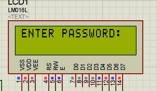
The "ENTER PASSWORD " statement will remain for a second and then it will vanish.At this point you will have to enter password which will be shown in terms asterisk " **** ".

The coding of the micro-controller is done such that only four numbers can be used to enter password. If you want to increase the length of the password you can do that by adding loops in the coding which will be dealt later. Here, in this project the password is set as 1234. when this password is entered the LCD will display "correct password" as shown below and the LED will turn on which is connected at port 1. you can set your own password by changing the password in the code.
If you want to set your password using the operators like " + ", " -" etc you can do it by setting the password in the code as follows:
If you want to set your password using the operators like " + ", " -" etc you can do it by setting the password in the code as follows:

- for " ON/C " =16
- for " + " =10
- for " - " =14
- for " = " =15
- for " x " =11
- for " ÷ " =13
programming:
The programming of the microcontroller is done using keil compiler.The codings for this project is explained below:#include "REGX51.H"
#include "delay.h" /*the header file of delay is added*/
#include "lcd.h" /*the header file of LCD is added*/
#include "keypad.h" /*the header file of keypad is added*/
#define relay P1_7;
void main()
{
int first_key,second_key,third_key,fourth_key;
P1=0X00; /*port 1 is defined as the output port*/
P2=0x00; /*port 2 is defined as the output port*/
P3=0xff; /*port 3 is defined as the input port*/
LCD_INIT();/* the LCD display is initialized */
LCD_STRING("PASSWORD BASED");/*displays PASSWORD BASED on the lcd*/
delay_sec(1); /* provides a delay of 1 second */
LCD_CMD(PUTLINE2);
LCD_STRING("LOCKING SYSTEM");
LCD_CLEAR(); /*clears the LCD display*/
LCD_STRING("ENTER PASSWORD:");
delay_sec(1);
LCD_CLEAR();
while(key_get()==NOKEY);
first_key=key;
LCD_STRING("*"); /*when any key is pressed display it as " * " */
while(key_get()==NOKEY);
second_key=key;
LCD_STRING("*");
while(key_get()==NOKEY);
third_key=key;
LCD_STRING("*");
while(key_get()==NOKEY);
fourth_key=key;
LCD_STRING("*"); /* by adding another while loop you can further increase the length of your password */
while(1)
{
if((first_key==1)&&(second_key==2)&&(third_key==3)&&(fourth_key==4))/*here, the password set is 1234. you can change the password over here.if you have increased your password length see that you also make changes in the If loop over here i.e by adding further &&fifth_key=....&& sixth_.. and so on */
{
LCD_CLEAR();
LCD_STRING("Correct Password");
P1_2=1; /* if correct password is entered make P1_2 high which will turn on the led */
delay_sec(2);
}
else
{
LCD_CLEAR();
LCD_STRING("Incorrect Password");
delay_sec(2);
}
} }
download files
You can download all the hex file, schematic diagram and codes over here:schematic diagram
codes
the .hex file
Instead of LED you can use any other application like motor which works using a relay or a buzzer and you can go on with many other application. If you have any questions with regards to the project or would like to improve this project further please feel free to comment.


