


Welcome back embedded system geeks! In this article we are going to learn about the interfacing of a Buzzer with the microcontroller. But if this is your first mini-project you should probably check-out my previous article on Blinking LED'S for more understanding of the programming I will be dealing with this project. Once you get to know what Buzzer is and the programming logic behind connecting a Buzzer and a microcontroller you will able to apply the same logic to any microcontroller (i.e. your microcontroller may be a PIC or an AVR microcontroller). At the end of the explanation of the code there are some questions for you to answer which can help you to improve your programming skills.
why do we need a Buzzer?
Buzzer is used many times in embedded systems. For an instance-Digital clock with an alarm-here buzzer can be used an alarm or a fire alarm or an intruder alarm. There are so many uses.
Components required
- 1 microcontroller 89C52(89S52 will also do)
- 1 potentiometer-10k
- 2 ceramic capacitors-22pF
- 1 switch(button for reset purpose)
- 1 electrolytic capacitor-10uF,25V
- 1 crystal oscillator-11.0592MHz
- 1 resistor-10k
- 5 LED's
- 1 resistor-1k
- 5 330 ohm resistor
- 1 Buzzer
- 1 transistor-BC548
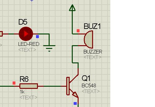
Schematic Diagram

This project has been made using Proteus software.If you want to learn more about the software you can watch the tutorials provided below
The connection of the circuit is explained below
- Port 2 of the microcontroller is defined as the output port
- Port 3 of the microntroller is defined as the output port
- 4 LED's are connected to the four pins of the output port 2 from P2.0 TO P2.3 respectively
- An LED is connected to the pin 3 of the output port 3 of the microcontroller
- A Buzzer is connected to the pin 8 of the output port 3
- Other components connected to the microcontroller are for the working of the microcontroller.
Working
The working of the circuit is shown with an application of a decade counter. As soon as the microcontroller receives a power supply, the counter will start counting. An image of the counter is shown below

The Decade counter will count from 0 to 9 and when the counter counts 9, the buzzer will be switched ON.The transistor connected to the buzzer acts as a switch.The programming of the microcontroller is explained below:
#include "REGX52.H"
#include "delay.h" /*delay header file is included*/
void main()
{
P2=0X00;/*port 2 is defined as output port*/
P3=0XFF;/*port 3 is defined as output as port*/
while(1)
{ P3_2=0; /*set pin 3 of port 2 to logic 0 */
P3_7=0; /*set pin 8 of port 2 to logic 0 */
P2=0X00; /*code for the decade counter begins here*/
delay_sec(1);
P2=0X01;
delay_sec(1);
P2=0X02;
delay_sec(1);
P2=0X03;
delay_sec(1);
P2=0X04;
delay_sec(1);
P2=0X05;
delay_sec(1);
P2=0X06;
delay_sec(1);
P2=0X07;
delay_sec(1);
P2=0X08;
delay_sec(1);
P2=0X09;
delay_sec(1); /* code for decade counter ends here*/
if(P2==0X09)
{ P3_2=1; /*LED is switched ON*/
P3_7=1; /*buzzer is switched ON*/
delay_sec(3); /*buzzer is switched ON for 3 seconds*/
P3_2=0; /*LED is switched OFF*/
P3_7=0; /*buzzer is switched OFF*/
}
}
}
Try this for Fun
Try to program your microcontroller in which the Buzzer is used as a musical device meaning your buzzer will output a musical tune .

9 comments:
where is the delay program....
Hello friend i really liked your website and specially all the things related to proteus simulations so i have featured your post in my website, Geniusdevils.
I am trying to produce melody with buzzer using pwm
but the sound is very low and notes are not at all clear. Sound increases on going on higher scales(around C6 note) but clearity doesn't.
Can you provide a circuit that solves this problem.
I have HXB buzzer. Its specifications from the Internet says that it is 42 ohms and resonant frequency is 2khz.
Any help is appreciated.
Thanx in advance.
I know the c language but i don't know the micro controller machine language like P2=0X00,P3=0XF etc
how can i learn this, can any one suggest?
how to create code and draw circuit pic18f4550
exercise
Sw1 = led1 on,buz on
sw2 = led2 on,buz off
where is an delay program??
the pgm will not RUN then without delay pgm
Thank you for sharing nice blog
MySQL Classes in Uttam Nagar
i need complete program
Post a Comment